CCS Signal Acquisition Film
High-insulation film for CCS signal acquisition FPCs in EV packs: 85/85 for 2000 h, anti-bleed at 150 C, halogen-free option, -40 to 125 C.
- Fast Delievery
- Quality Assurance
- 24/7 Customer Service
Product Introduction
Products Description
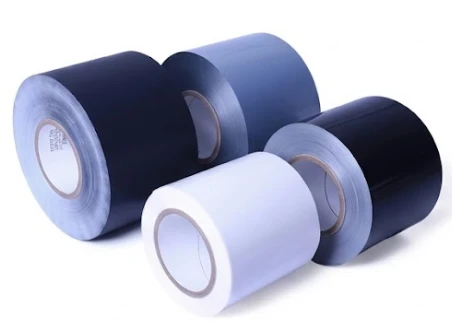
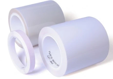
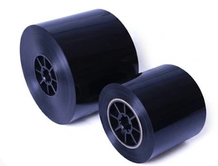
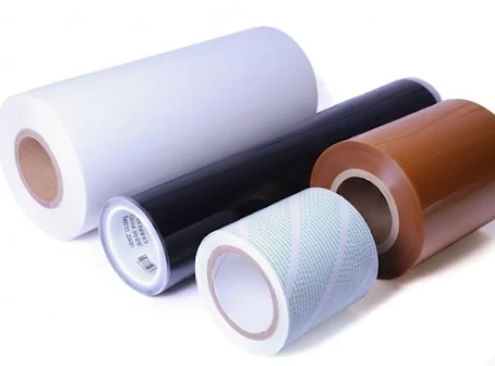
CCS Signal Acquisition Film for Lithium Battery Sampling Circuits
A cell contact system does two electrical jobs in the same laminated part. One is carrying current between cells. The other is measuring, and the measurement is what the BMS uses to decide whether the pack is safe. The first job tolerates a milliohm of resistance drift. The second does not tolerate a millivolt.
This film exists for the second job: the adhesive layer that bonds the voltage and temperature sampling circuit to the CCS, insulates it from the busbar beneath, and has to keep doing both without disturbing the reading.
| At a glance | |
|---|---|
| Continuous temperature | -40 °C to 125 °C |
| Damp heat | 85 °C / 85 % RH × 2000 h |
| Anti-bleed | Pass at 150 °C × 48 h, no flow past the bond area |
| Solder excursion | 185 °C × 5 min |
| Flame retardant option | Halogen-free system reaching VW-1 |
| Failure signature | Measurement drift, not breakdown |
Recommend product
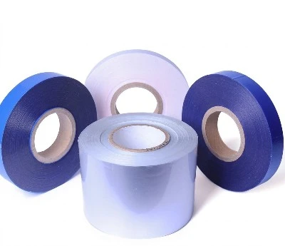
Signal acquisition film vs busbar insulation film
This is the question that produces the most wrong orders in the CCS category, because both products are sold under a "CCS film" heading and both are thin, flame-retardant adhesive films.
The short answer: the insulation film is the dielectric barrier between the busbar and anything at a different potential. The signal acquisition film is the bond and insulation for the low-voltage measuring circuit that sits on top of the assembly. One protects the pack from high voltage; the other protects the accuracy of the numbers the BMS acts on.
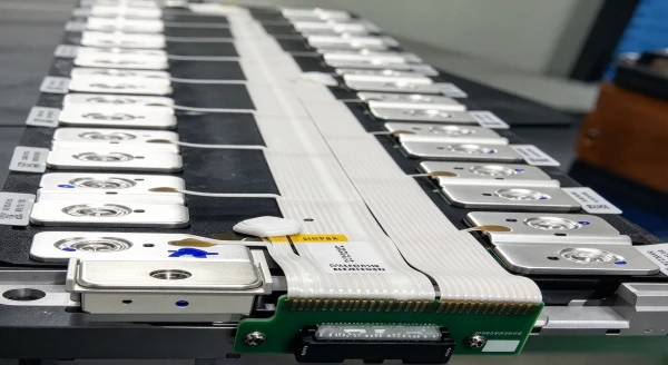
The long answer, attribute by attribute:
| Attribute | CCS signal acquisition film | CCS laminated busbar insulation film |
|---|---|---|
| Primary function | Bond and insulate the sampling FPC; preserve measurement integrity | Dielectric barrier between busbar and module structure or adjacent conductors |
| What it touches | FPC or sampling harness, connector, NTC | Aluminium or copper busbar, module frame or tray |
| Governing electrical property | Insulation resistance stability over life | Withstand voltage and breakdown strength |
| Failure mode | Voltage or temperature reading drifts, contact becomes intermittent | Hipot failure, short circuit, tracking along an edge |
| Detectable in production? | Often not - drift appears in the field | Usually yes, at the hipot station |
| Damp heat qualification | 85 °C / 85 % RH × 2000 h | 85 °C / 85 % RH × 1000 h |
| Continuous temperature | -40 °C to 125 °C | -40 °C to 125 °C |
| Flame rating | Halogen-free option reaching VW-1 [TBC: standard grade rating] | UL 94 VTM-0 |
| Adhesive system | 125 °C platform, anti-bleed controlled | Polyurethane or epoxy |
| What sets the thickness | NTC thermal response plus dielectric spacing to the busbar | System voltage and insulation coordination |
| Dominant process risk | Adhesive bleed into a connector cavity or contact window | Voids at a burr, unsealed cut edge, adhesive in a weld window |
| Who specifies it | BMS / electrical design, test and validation | Pack mechanical design, safety and EMC |
Why they will not substitute for each other
The two films are qualified against different acceptance criteria, so a swap is not a substitution - it is a new qualification:
Insulation film used as the sampling bond loses the anti-bleed control that the sampling application depends on, and its chemistry is qualified to 1000 h of damp heat rather than 2000 h. The likely outcome is adhesive in a contact window, which reads as a cell voltage offset.
Signal acquisition film used as the busbar barrier is qualified for measurement stability rather than for withstand voltage, and its flame rating is grade-specific rather than a blanket VTM-0. The likely outcome is a hipot failure or a flame test non-conformance.
Neither statement claims the film cannot do the job. It claims the job has not been tested on it, and in a pack that difference ends up in a validation report rather than a datasheet.
If your assembly needs both
Most CCS designs do. They are laminated in sequence onto the same busbar, and the interface between them is where a mismatch shows up - typically as an adhesive-edge interaction at the boundary, or as a thickness step that changes the sampling FPC standoff. Send both drawings together and they can be quoted and reviewed as a pair.
The sampling chain, and where the film sits
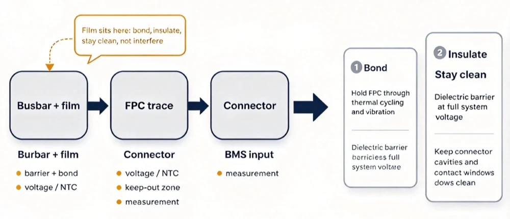
That sentence is why this product is specified differently from an insulation film. A delaminated busbar barrier fails loudly - at a hipot station or in a fault event. A degraded sampling interface fails quietly: the pack still works, the readings drift, and the BMS makes decisions on numbers that are no longer true.
Four jobs, and the fourth is the one that gets missed
| Job | What it means in the assembly |
|---|---|
| Bond | Hold the FPC to the busbar or carrier through thermal cycling and vibration, without creep |
| Insulate | Provide the dielectric barrier between sampling traces and busbar at full system voltage |
| Stay clean | Not flow into connector cavities, contact windows or wire-bond areas during lamination |
| Not interfere | Keep insulation resistance stable over life, so the measurement does not drift |
The fourth job rarely appears in a specification and is routinely discovered in the field. It is a materials property, not a process property: ionic contamination and moisture uptake in the adhesive change the leakage path, and a changed leakage path changes what the BMS reads.
2000 hours, not 1000
The insulation film for the same assembly is specified at 1000 h of damp heat. This film is specified at 2000 h, and the difference is not marketing - it follows from the failure mode:
A barrier fails by breakdown, which is detectable and binary.
A sampling interface fails by drift, which develops slowly, appears after the first year, and is invisible to both incoming inspection and production hipot.
Doubling the exposure is the only way to see drift that begins at 1500 h. A film that passes 1000 h and hydrolyses afterwards passes every test the factory can run.
Why the adhesive chemistry decides the result
In this class, damp heat endurance is set by the adhesive rather than the carrier. Same construction, same test, two chemistries:
| Adhesive chemistry | 85 °C / 85 % RH endurance |
|---|---|
| Conventional polyester hot melt | 96 h before delamination |
| Low-hydrolysis polyolefin platform | 2000 h, no delamination |
Twenty-fold, from a layer a few tens of microns thick. It is also why the phrase "high humidity resistance" is meaningless in a datasheet without the hours attached to it - and why a supplier quoting "excellent humidity resistance" should be asked for the duration and the sample size.
Failure modes that show up as measurement error
1. Adhesive bleed into the connector or contact window. The most common and most expensive. Adhesive that flows during lamination reaches a contact surface, joint resistance rises or becomes intermittent, the pack passes end of line, and the vehicle reports a cell voltage offset at 3000 km. The platform is tested for anti-bleed at 150 °C × 48 h with no flow past the bond area.
2. Insulation resistance drift from moisture uptake. Not a short - a slow fall in resistance between the sampling trace and the busbar. The measurement chain sees an offset, and the BMS compensates for a fault instead of reporting one.
3. Delamination at a cut edge. Slitting leaves an exposed interface. The edge lifts first under thermal cycling, and a partly bonded FPC behaves like a cantilever: it flexes at the boundary and eventually cracks a trace.
4. Loss of thermal contact at the NTC. Where the sensor is bonded through the film stack, the thermal path runs through the adhesive. A void does not cause a failure - it causes a slow response, so pack protection reacts late to a fast thermal event. This is the failure mode most often designed in without anyone noticing.
5. Tracking along a contaminated surface. At 800 V the creepage path between a sampling trace and the busbar edge is short by design. Surface contamination plus moisture converts it into a tracking path, and tracking resistance is a property that has to be specified, not assumed.
Platform performance
| Property | Value |
|---|---|
| Continuous temperature range | -40 °C to 125 °C |
| Damp heat resistance | 85 °C / 85 % RH × 2000 h |
| Long-term heat aging (platform) | 125 °C × 1000 h |
| Anti-bleed (platform) | Pass at 150 °C × 48 h, no flow past the bond area |
| Short-term excursion (platform) | 185 °C × 5 min, covering connector soldering |
application


certificate

Where it is specified
| Application | What the film is doing |
|---|---|
| EV battery pack voltage sampling FPC | Insulating and bonding the sampling circuit over the busbar |
| Module temperature sensing (NTC) | Mechanical anchor and thermal path to the sensor |
| Prismatic and cylindrical cell module CCS | Same duty at higher packing density, with tighter bleed control |
| Energy storage rack BMS sampling | Longer service life, lower peak temperature, same insulation requirement |
| Consumer electronics battery pack | Smaller geometry, thinner film, tighter keep-out |
Design guidance
Draw the keep-out zone before choosing the film. Adhesive flow is a property of the adhesive at your press conditions, not of the operator. Define the distance from the bond area to every contact window, connector cavity and wire-bond pad, then confirm flow against that distance.
Specify tracking resistance explicitly at 800 V. On a 400 V architecture, creepage is usually comfortable. At 800 V the sampling trace sits much closer to busbar potential than intuition from a 400 V programme suggests, and tracking resistance becomes a selection criterion rather than a datasheet line.
Treat the NTC as a thermal design, not a bonding point. If the sensor is bonded through the film, adhesive thickness sets the thermal resistance between cell and sensing element. A thicker film for dielectric margin makes the response slower. State the response time requirement and let the thickness follow from it.
FAQ
What is the difference between CCS insulation film and signal acquisition film? The insulation film is the dielectric barrier laminated onto the busbar and is qualified by withstand voltage. The signal acquisition film bonds and insulates the sampling circuit on top of the assembly and is qualified by insulation stability - 2000 h of damp heat rather than 1000 h, because its failure mode is measurement drift rather than breakdown.
Can one film do both jobs? Not on the evidence either product carries. Each is qualified against a different acceptance criterion, so using one for the other re-qualifies it from scratch. If a single film is a hard requirement for your design, raise it as a development request rather than assuming equivalence.
Why does the sampling film need 2000 hours of damp heat when the insulation film needs 1000? Because the consequence differs. A barrier fails by breakdown, which is detectable. A sampling interface fails by drift, which is not. The longer exposure is what separates a film that stays electrically stable from one that merely survives.
Will the adhesive flow into our connector during lamination? That is the specific risk this platform is tested against: anti-bleed at 150 °C × 48 h with no flow past the bond area. The remaining variables are your press pressure and your keep-out distance, which is why we ask for the drawing rather than quoting a film alone.
Can it survive soldering the connector after lamination? The platform is qualified to 185 °C × 5 min, which covers a connector soldering excursion. If your process runs hotter or longer, say so - the answer changes.
Do you have a halogen-free version? Yes, with a halogen-free flame retardant system reaching VW-1. Confirm the grade at enquiry stage: halogen-free is a grade, not a property of the whole family.
What thickness should we use under an NTC? It follows from the response time you need, not from the dielectric requirement alone. A thicker film gives more dielectric margin and a slower thermal response. Send the response time and we will quote against it.
Hot Tags: ccs signal acquisition film, China, suppliers, wholesale, buy, price
No Information